Understanding Automotive Electrical Switch Relay Diagram
In front we discuss troubleshooting relay-related wiring, rent's brushup. Endmost calendar week we talked about the standard Blaring Numbers used happening relays and the incredible public-service corporation they represent.
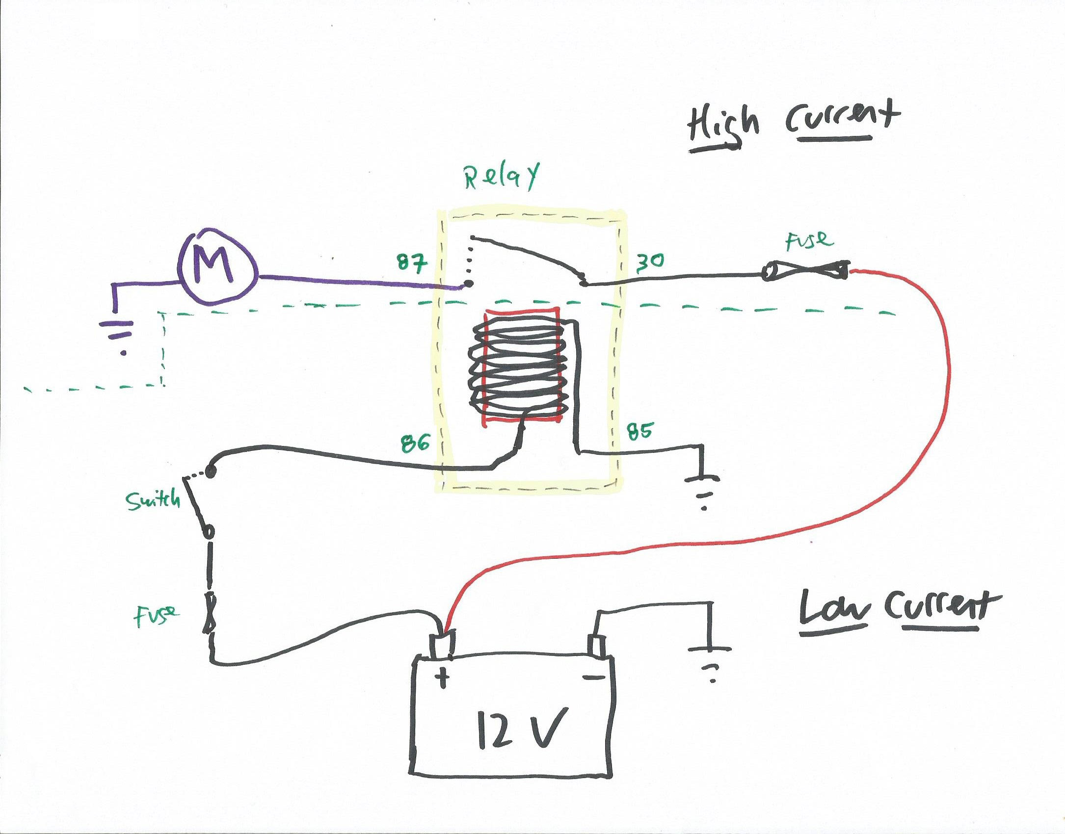
In any circuit with a DIN relay, without sounding at a wiring diagram, you know that:
- Terminal 86 supplies power to the relay's internal electromagnet.
- Period 85 grounds the electromagnet.
- Endmost 30 supplies power to united of the internal switch contacts.
- Terminal 87 connects the other internal switch impinging to the device controlled by the electrical relay.
- When you power terminal 86 and ground terminal 85, it energizes the electromagnet, which pulls the internal switch contacts closed, which connects 30 (power) to 87 (the gimmick), which sends power to the device.
Thereupon taken, you can easily troubleshoot any circuit that uses a electrical relay. For those who prefer the left-brain, lay-it-out-in-a-table set about:
| Terminal | Which Circuit? | Definition |
| 86 | Low current (manipulate) | Electrical relay coil + (great power stimulation) |
| 85 | Low current (control) | Electrical relay coil – (ground) |
| 30 | High current (load) | From battery + |
| 87 | Piping current (load) | Output to device, unremarkably open, pulled closed when coil is energized |
| 87a | Soprano current (load) | Only used on unary-pole double throw (SPDT) "changeover" relays. Output to former device, normally closed, pulled open when coil is energized |
And for those who prefer right-brain pictures, eminence that the photo doesn't show the 87a terminal, as this is exclusive used by single-pole-double-throw "changeover" relays that are fewer commonly used than the four-terminal single-pole-single-bedevil (SPST) relays described here.
Electrical relay vs. Socket DIN numbers
When troubleshooting relay-germane wiring, you need to be very clear about the DIN numbering and non jumble the numbering on the underside of the relay with the numbering on the socket the relay plugs into. They are the mirror-image of for each one other.
The DIN terminal numbers are nearly always embossed on the bottom of the relay. They may operating theatre may not be stamped on the socket the relay plugs into. If they're not, just take a sheet, draw the terminals thereon (each terminal drawn correctly, either vertically or horizontally, so they accurately reflect the relay), and so label the terminals mirrored left to opportune from how they are on the seat of the relay. Then lay the paper next to the socket.

Trouble-shot the electrical relay itself: Does the electrical relay click?
As I have stated several times previously, every mechanical relay has a little electromagnet in IT, and when it is energized it pulls the intramural switch contacts in concert. That makes an audible clicking sound. You also throne feel the contacts terminative if you lay your hands along the relay.
So, for example, if your horn doesn't work, the first thing to do is turn it on (e.g., attain the horn push button), and listen to and spirit the relay. If you hear Beaver State flavour the relay click, the relay and its wiring aren't the problem. But if it's not clicking, the trouble could be in the electrical relay itself operating theater in the wiring. You need to fig taboo which.
To test the electrical relay itself, take two wires, each around a foot long with a female jigaboo terminal at one close and stripped at the other end. Attach one spade connector to relay terminal 86 (coil +). Attach the other to relay terminal 85 (coil ground). Touch the 86 wire to the battery's positive post, and the 85 wire to the stamp battery's negative berth. Actually, unless the relay has a crystal rectifier in it, it won't matter if the sign is switched; the electromagnet testament be energized regardless. You should hear and palpate the relay click. If you don't, the relay isn't working. Replace it.

For extra credit, you can set a multimeter to evaluate conductivity (resistance) and connect it crosswise relay terminals 30 and 87. When you touch 86 and 85 to the assault and battery, the electromagnet pulls the switch contacts together, then the resistance between 30 and 87 should read essentially zero (under one Georg Simon Ohm). If it doesn't, the relay isn't functioning. Supplant it.

If your electrical relay is a SPDT "changeover" relay, you can severally monitor the switch in continuity from 30 to 87 and then from 30 to 87a to aver the switch starting and closing for both of the high-current paths.
If the relay does click and 30 and 87 do show persistence, there is still the possibility that the internal contacts are corroded and a voltage drop across them is preventing full phase of the moon current from flowing. Take that thought and park it for a moment.
Testing the relay wiring
If the relay itself tested as good, then the relay wiring must be tested succeeding. As with most relay-affinal things, it's best to think about this in damage of low current (control side) tests, and high current (load side) tests. Consult the DIN table and the figure above.
Test the low current (control slope). Set back the multimeter to measure voltage, connect the black probe to establish, and use the red probe on socket depot 86. Turn the circuit on (e.g., depend on the drive, flash the headlights, beep the horn, whatever information technology is you'rhenium testing) and verify that 12V is present connected 86 when the button is pushed, and it vanishes when the button is discharged.
[insert pic: img_2465. Legend: "Testing for and finding voltage at socket terminal 86."]
And so test 85 by setting the multimeter to measure resistance, probing socket terminal 85, and making sure that there is continuity betwixt information technology and ground. (Note that if the circuit is for a motor horn, most horns are switched happening the negative side of the control circle, not connected the advantageous. That is, on a horn, 12V should always be show on 86, and 85 is grounded when the horn button is pressed).
If the control side fails either of these tests, you must troubleshoot the wiring. Often it is a problem in whatever is switching the control side on and murder. E.g., on a tusk, the problem is often in the spring-besotted speculator behind the wheel that touches the ring contact that grounds terminal 85.
On the high current (load side), test that 12V is present on socket concluding 30, and that thither is continuity between 87 and the device. Note that, on some grey cars, 30 and 87 may be switched—that current flows in 87 and out 30 instead of the way information technology reads in the Rumpus table. As long as the relay doesn't have a diode in it, that's fine. IT's just a switch. Current commode flow in and out either pull of the switch. If the only affair you find wrong is that 87 is ever hot and 30 goes to the device instead of the other direction roughly, don't worry about it.
Jumpering Crosswise the Relay
If the circuit passes the high current (load side) tests, you should be able to simply pinny across terminals 30 and 87 to ignite the device. Remember: All that a relay is doing is remotely copulative 30 to 87, so in manually connecting 30 to 87 with a jumper, you'Re non doing anything the relay isn't doing. Ahead you do this, remember that this is the high current side of the electrical relay, and a shell out of current may begin flowing through your jumper wire equally presently as you make contact, creating a burn hazard. It is best to de-stimulate terminal 30 first by shutting disconnected the ignition, but on some cars, 30 English hawthorn quiet equal hot even with the kindling off.
Take up a robust piece of conducting wire (at least 12 gage) or so 6 inches long and crimp a male spade pole to each end.

Shut the ignition off. Use a multimeter to measure the voltage at socket terminal 30 and verify that information technology is off. If it's not, wear gloves then any sparking Oregon heating of the pinny wire doesn't burn you.
Stopper one goal of the jumper into socket terminal 30, and the former end into socket terminal 87. If there's voltage on 30, you may watch a modest spark when you plug the pinny into 87. The device should turn connected. If information technology does, at that place is no trouble with the high current (load) side wiring, and the problem must be either in the relay or in the control side wiring.

If your relay is a SPDT "changeover" relay, you can independently jumper 30 to 87 and then 30 to 87a to manually test the turn-on of both squeaking-current loads.
If you've done these tests and have soundless not figured out why the device doesn't turn on, the problem is belik that either the device itself is bad, there's a high-underground failure in the relay's internal switch contacts, or there's a break in the path between the device and ground.
I don't usually hawk my electrical book, but there is a highly-detailed chapter on relay circuit troubleshooting containing greater depth than I'm able to go into here.
So that's it. Relays and the circuits that use them are really pretty simple. Upright keep repetition … "It fair connects 30 to 87… it hardly connects 30 to 87…" You'll be fine.
***
Overcharge Siegel has been written material the column The Hack Mechanic™ for BMW CCA Roundel Magazine for 30 geezerhood. His refreshing book, Ran When Parked: How I Road-Tripped a Decade-Suddenly BMW 2002tii a Thousand Miles Back Home plate, and How You Can, To a fault, is available here connected Amazon. Additionally, he is the author of Memoirs of a Hack Mechanic and The Hack Mechanic™ Guide to European Automotive Electrical Systems. Both are available from Bentley Publishers and Amazon. Or you can put personally carven copies through Rob's website: www.robsiegel.com.
Source: https://www.hagerty.com/media/maintenance-and-tech/understanding-relays-part-3/
Posted by: ziziesheart.blogspot.com